Business Process Flow Framework for MVC - Part 1
Abstract: A state machine based process framework for web.
- The Problem Statement
- Core Tenets and Solution Architecture
- Why a State Machine?
- Working in MVC
- Conclusion
- Footnotes
The Problem Statement
So a while back I was working with a client who had an enterprise system to help manage the various business processes they had. Since the programme started circa 2007, most processes were implemented in a portal written in WPF that was served via remote desktop throughout their branches.
Given that times had changed (ca. 2013), there was of course some interest in experimenting with alternative distribution channels like web.
The thing that always bugged me about building business processes in web was that most of the time, the “next” step was basically hard coded into the next button of each of the views - and of course, this leaves the problem of it being difficult to know what your process then actually looks like, never mind maintain it.
So after some thought (and combined previous experience maintaining processes in web), I decided that the way I like to build processes is to have them backed by a state machine, and that the web-app should simply be a display for that state machine.
Core Tenets and Solution Architecture
And so I set about making a framework for Asp.net MVC with the following characteristics:
- The process is backed by a state machine
- The process definition should be separated from it’s implementation
- The process definition should be declarative (making it easy to analyse)
- The UI layer should ask the process what to show
- The UI layer should not need to know about the process directly
- The views should be lightweight and ideally cacheable
- As per above, view data should be loaded separately
- The process state should live on the server (your session lives there)
Bearing in mind that this framework was built to fit in with an existing services architecture. The layer’s for the system are as follows:
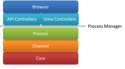 Layer stack: “Core” and “Channel” refer to the repository and “Business Logic” layers in the existing architecture. The browser communicates with both the API and View layer components which source their information from the process layer via a “process manager” intermediary.
In the above figure, note the Process Manager. This guy, who is a mediator, is an important architectural element that binds the presentation layer (blue layers) with the process layer (green).
In component diagram form, these elements look like this:
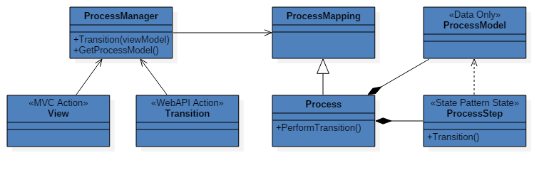 Components: Note that there is no direct interaction between the views/apis and the processes (implementing process mapping).
All data for the business process is stored in the <<Data Only>> Process Model. The function of the process is to guide the user through creating a process model which can then be used to perform a business function. Each process step has it’s own class (state), and the process class itself becomes very thin, delegating it’s work to the current process step - i.e. the State Pattern1.
A process implements a process mapping. This is a little different to a normal OO implements, since the process mapping is an interface that includes mapping meta data. I.e. there is a logical model which contains information about how the presentation layer must consume or be bound to the process.
The purpose of this design is that the complexity of navigating from step to step is hidden from the presentation layer, as that layer has no business “knowing” which step to go to next. It should ask the process which governs it, and does so via a mediator.
This in turn allows the navigation complexity to be managed in an encapsulated way that is suitable to process flow - which I have chosen to implement using a state machine.
Why a State Machine?
State Machines are great at managing complexity in situations where you have units of work which are effectively isolated in their function but must exist in a collaborative way with other units. In other words, you have multiple states, each with their own behaviours, but must transfer to other states.
This allows us then to model a business process like this:
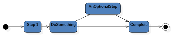 States: A sample business process. Each state, or activity may have it’s own complexities, but are contained within the state.
Just a minor note on State Machines vs the State Pattern: These are not the same thing, however the state pattern can be used to implement a state machine.
Working in MVC
So now that the architecture has been planned out, what does this look like in MVC?
As one can imagine, the views are anaemic and coded in razor template, served by an MVC controller, while the data is provided through WebAPI controllers serialising to JSON.
The MVC actions are purely for addressing purposes and have no logic in them, and the Api actions delegate any “business logic” to the process itself and simply map the response from the Process Model.
With some interception of the API calls we can then provide process meta data which allows a Single Page Application running in the browser to know which API calls and views to fetch next. All that then remains is bootstrapping a process which can again be performed by provided the SPA with the process bootstrap meta data.
Well that seems simple enough… right? There’s a little more “magic” to the implementation, but in a nutshell, yes, thats it!
Here is an overview of the WebAPI life cycle for an API call:
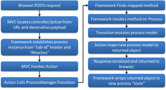 Life Cycle: The process framework life cycle. Most of this work is performed by the
 Process Manager.
Conclusion
This concludes part 1 of this series on the process framework I wrote. In my next post, I’ll go into details of the process definitions and project layout in Visual Studio.